


Issue 8 – August 2022
When is 8+8 not equal to 16 and what has that got to do with the size of pizza? Pump expert Harry Rosen unravels the relationship between flow rate, pipe area and velocity and the effect these values can have on the friction losses of a piping system.
Parallel pipes and the size of pizzas
I recently worked on a pumping project where the engineer sizing the pipeline thought that rather than specifying one 16″ pipe, he would use two 8″ pipes in parallel. Simple mathematics suggests this should be OK, that is 8+8=16. Half the flow goes through each smaller pipe and so the velocity in the smaller pipes should be the same as the velocity in the large pipe. Wrong!
I also had a heated debate with one of my pump course delegates who could not grasp the relationship between the increase in friction losses through a pipe and the velocity in the pipeline. In the end I realized he was getting stuck on the difference between flow rate and velocity.
Both of the above cases got me wondering whether one of the basic principles of pump systems is actually misunderstood– the relationship between flow rate, pipe area and velocity.
The formula for flow through a pipe says that Flow (Q) equals fluid velocity times pipe area (Q=VA). This means that with constant flow, if we halve the area we would double the velocity. In our case we would be halving the flow rate in the smaller pipes so therefore the velocity would remain unchanged. This is what the engineer was counting on when he proposed two 8″ pipes rather than one 16″ pipe.
But he was probably confusing area with the pipe diameter, and we know the formula for area of a pipe A=πD²⁄4. Area is proportional to diameter squared, so what effect does this have on the velocity?
Let us take a step back and replace the pipes with pizza, we should all know (at least sub-consciously) that the area of an 8″ pizza is a lot smaller than half the area of the 16″ size. Think of how big a 16″ pizza would be (watch any American TV show and you will often see them eating one of these monster pizzas). Our largest pizza is around 12″, which is only around half as big (because of area) as the 16″. That is why pizzas increase in small increments of diameter as the relationship between pizza size (area) and diameter is a squared relationship.
This means that an 8″ pizza is one quarter the size (area) of a 16″ pizza, not half the size, which also means the area of the 8″ pipe is only one quarter the area of the 16″ pipe! It follows that installing two 8″ pipes (or buying two small pizzas) only gives you half the area of the original 16″ pipe, the equivalent of halving the pizza area of the monster 16″.
Why is the area so important? Well that is easy to answer for pizza as you are going to end up hungry if you were expecting the equivalent of a large 16″ pizza when buying two 8″ pizzas. But this is where the pizza analogy breaks down so back to the humdrum of pumping systems.
When we have two parallel pipes of half the diameter, we get half the flow rate going through each pipe, but one quarter the area for each pipe. To maintain the continuity equation for flow (Q=VA) at half the flow rate, the velocity in the smaller pipes will be double the velocity of the one large pipe.
And twice the velocity is bad. Really bad. Think of the COVID curve, with the rate of infections growing exponentially, surging upwards at ridiculously steep rates. This is what happens with friction in a pipeline as the velocity increases, which it will if the diameter reduces.
The equation for friction loss within a pipeline states that friction is proportional to velocity squared, so small increases in velocity create large increases in friction. Doubling the velocity will quadruple the friction and in our suction pipe design above, instead of around 1m of friction loss, the system must now handle losses of over 4m.
This doesn’t sound like a lot, but the problem piping in this case was on the suction side of the pump. And even worse, the application was to pump out of a submerged pit, which made the suction friction losses even more critical. In terms of NPSH (net positive suction head) and cavitation, the 4m of friction reduced the NPSH available in the system by 4m, which became less than the NPSH required by the pump, resulting in the brand new pump cavitating the first time it was operated.
Back to the consultants, and the good news that they did learn from their mistake. A single 16″ diameter suction pipe was installed and the suction problems disappeared. When it came to sizing the discharge piping, 1 250m of overland pipeline, they did not make the same mistake and again selected one pipe with a 16″ diameter. If they had gone for two pipes, they would have two 12″ pipes to give the same friction loss as the single 16″ pipe.
So if friction is proportional to velocity squared, and velocity is proportional to diameter squared, it follows that increase in friction is proportional to reduction in diameter to the 4th power – actually to the 5th power as you will see from the derivation shown. Small reductions in diameter will result in very large increases in friction loss. So pipe friction in a pipeline increases at a massive rate as the diameter reduces, way steeper than even the COVID curve mentioned above.
The derivation of the relationship between pipe friction and internal pipe diameter
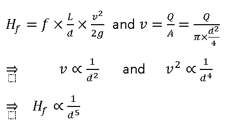

Why is this important? We are not talking about new systems where design houses, consultants and system designers are aware of this relationship and should take it into account in their design. It is much more of an issue with existing systems and what happens to pipeline friction over time with the buildup of scale and deposits within the pipe. This has exactly the same effect as reducing the pipe diameter, with the increase in friction proportional to the reduction in diameter to the 5th power.
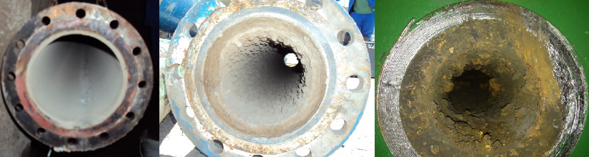
Excessive build-up of scale, sand and silt in pipelines leads to increases in friction losses and a dramatic reduction in flow rate.
The increase in friction head translates into wasted energy, as thousands of kWh are wasted overcoming the friction head. But there is a more serious effect for centrifugal pumps – the higher friction head pushes the pump back on its curve toward shut off, resulting in reduced flow rate and, in many cases, a pump which can no longer supply the flow rate required by the system.
I have seen this many times in applications around the world, where over time the pump station delivers less flow rate, even though the pumps have been recently refurbished and are in good condition. Examples include:
- A cooling water system for a petrochemical plant cannot supply sufficient cooling water for the plant, forcing the plant to operate at reduced capacity.
- An abalone (perlemoen) farm pumping seawater has to clean out their pipes every 2-3 months as a result of all the organic growth on the inside of the pipes dramatically reducing the flow through the system
- A water supply company cannot supply the community’s needs due to sand and silt depositing in their pipelines. As a result, water rationing is required even though there is a plentiful supply of water available.
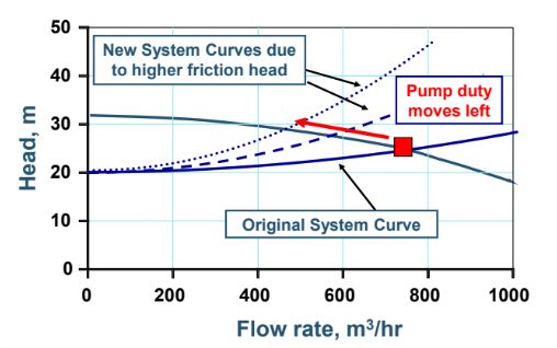
On a centrifugal pump curve, the increase in friction head pushes the pump back on its curve toward shut off, resulting in reduced flow rate.
What are the cost implications? Over and above the increase in kWh required to pump the same amount of fluid, the cost of reducing plant output because the cooling system cannot pump sufficient cold water through the plant could be millions of Rands a day in lost production. I have even seen cases of political unrest as a result of water restrictions being imposed, not due to low dam levels, but due to pump stations not able to pump at their design capacity anymore.
This most often happens in parallel pumping systems designed to operate say three pumps to get the required design flow. As the pipeline internal diameter reduces over time, even operating four or five pumps the operators may not achieve the required flow they used to get with only three pumps running.
Refurbishing the pumps to brand new will not make any difference, either. Neither will replacing the pump with a more efficient model from another pump company. This is a system issue, and the culprit is pipe friction and its alarming relationship with pipe diameter.
What is the solution?
- Select pipe sizes for a new project to give low velocities: less than 1.0 m/s on the suction side and 1.5 to 2.0 m/s for pumping clear liquids.
- Choose discharge pipe velocities only slightly higher than the settling velocity for slurry pumping systems.
- Regularly clean out the pipelines, including chemical cleaning or high pressure washing. This could also be done using Pigs: projectiles sent down the pipeline which scour out the internal diameter of the pipe and return it back to its original size.
- In extreme cases, it might be necessary to replace the piping with larger diameter pipes to increase the area, reduce the flow velocity and drastically reduce the friction head.
In the Next article we take the pizza scenario one step further to help understand Bernoulli’s equations and friction loss within a pipeline, in an article titled ‘Using Luigi to decode Bernoulli’.
